Difference between revisions of "Using PSoC Creator"
(→Adding Drivers) |
(→Systick) |
||
| (12 intermediate revisions by the same user not shown) | |||
| Line 6: | Line 6: | ||
* PSoC Creator 3.3 CP3 | * PSoC Creator 3.3 CP3 | ||
* PSoC 5LP Prototyping Kit (CY8CKIT-059) | * PSoC 5LP Prototyping Kit (CY8CKIT-059) | ||
| + | * ILI9341 display module with SPI interface | ||
However, this article has been kept as generic as possible and should be usable for any PSoC platform. | However, this article has been kept as generic as possible and should be usable for any PSoC platform. | ||
| + | |||
| + | The complete pre-configured & ready-to-run example project of this guide can be found [https://community.ugfx.io/files/file/16-psoc-5lp-ili9341/ here]. | ||
== Structure == | == Structure == | ||
| Line 57: | Line 60: | ||
# Copy the [[Board File|board file]] template from the driver directory to your project (<code>board_ILI9341.h</code> in this case) | # Copy the [[Board File|board file]] template from the driver directory to your project (<code>board_ILI9341.h</code> in this case) | ||
# Add the driver source file to the project tree (<code>gdisp_lld_ILI9341.c</code> in this case) | # Add the driver source file to the project tree (<code>gdisp_lld_ILI9341.c</code> in this case) | ||
| + | |||
| + | == Hardware == | ||
| + | Unlike conventional microcontrollers, the PSoC family doesn't have pre-made peripherals. This section gives examples to implement some of the basic features required to create a useful & run-able µGFX application. | ||
| + | Please note that the components and their configuration shown here are '''examples'''. They are in no way optimized for a specific target or a specific application. | ||
| + | |||
| + | === Systick === | ||
| + | If running µGFX [[BareMetal|baremetal]] on the PSoC (without an underlying operating system), two systick functions have to be implemented ''(see [[BareMetal|baremetal]] for more details)''. The standard components library of the PSoC Creator schematic editor doesn't feature a pre-made systick component. Therefore, this has to built manually using a conventional timer and a counter. | ||
| + | |||
| + | In this example, we are using a 1 kHz timer and a 32-bit counter. However, other setups are possible: | ||
| + | |||
| + | [[File:psoc_systick.png]] | ||
| + | |||
| + | The two systick functions of the raw32 port can be implemented like this: | ||
| + | <source lang=c> | ||
| + | systemticks_t gfxSystemTicks(void) | ||
| + | { | ||
| + | // We use a counter with a 1kHz clock source | ||
| + | return Systick_Counter_ReadCounter(); | ||
| + | } | ||
| + | |||
| + | systemticks_t gfxMillisecondsToTicks(delaytime_t ms) | ||
| + | { | ||
| + | // We use a counter with a 1kHz clock source | ||
| + | return ms; | ||
| + | } | ||
| + | </source> | ||
| + | |||
| + | However, we still have to manually start and enable the timer and the counter. For this, we add another function and modify the | ||
| + | <source lang=c> | ||
| + | void raw32Init(void) | ||
| + | { | ||
| + | // Initialize the systick components | ||
| + | Systick_Timer_Start(); | ||
| + | Systick_Counter_Start(); | ||
| + | } | ||
| + | </source> | ||
| + | Now we use the <code>GFX_OS_PRE_INIT_FUNCTION</code> configuration macro in the [[configuration|configuration file]] to tell µGFX to call this initialization function that enables the systick components before doing anything else: | ||
| + | <source lang=c> | ||
| + | #define GFX_OS_PRE_INIT_FUNCTION raw32Init | ||
| + | </source> | ||
| + | |||
| + | '''''Note:''' There is also an unofficial systick component available from a Cypress employee at the Cypress forum. The advantage of that component is that it uses the native systick timer of the Cortex-M. The reason that component isn't used in this example is because it's not part of the official Cypress libraries. [http://www.cypress.com/forum/psoc-community-components/systimers-component Link].'' | ||
| + | |||
| + | === SPI === | ||
| + | In our example project we are using an ILI9341 display module connected over SPI. For this, we need to add an SPI component to the PSoC project and wire it up to the external pins to which the actual display is connected to. | ||
| + | |||
| + | [[File:psoc_spi.png]] | ||
| + | |||
| + | [[File:psoc_spi_config_01.png]] | ||
| + | [[File:psoc_spi_config_02.png]] | ||
| + | |||
| + | Note that in case of you want to connect a touchscreen controller with an SPI interface you want to use a second SPI component that is dedicated to the touchscreen. Using the same SPI component for both the display and the touchscreen '''massively''' restricts the display performance. | ||
| + | |||
| + | == Examples == | ||
| + | Various example projects can be found in the [https://community.ugfx.io/files/category/2-example-projects/ downloads section]. Use the search to find projects that suit your setup. | ||
Latest revision as of 00:43, 18 August 2016
This article will explain how the µGFX library can be added to an existing PSoC Creator project.
Contents
Used Tools
The following tools were used to create this guide:
- PSoC Creator 3.3 CP3
- PSoC 5LP Prototyping Kit (CY8CKIT-059)
- ILI9341 display module with SPI interface
However, this article has been kept as generic as possible and should be usable for any PSoC platform.
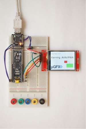
The complete pre-configured & ready-to-run example project of this guide can be found here.
Structure
We recommend using the following folder structure:
.
├── Project 1
├── Project 2
├── Project 3
└── ugfx
Adding µGFX
This guide will describe how to add the µGFX library to a PSoC Creator project using the Single-File-Inclusion technique.
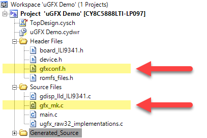
The first step is to add the file gfx_mk.c which can be found in the /src directory of the µGFX library directory to the project. Furthermore, we add our configuration file as well.
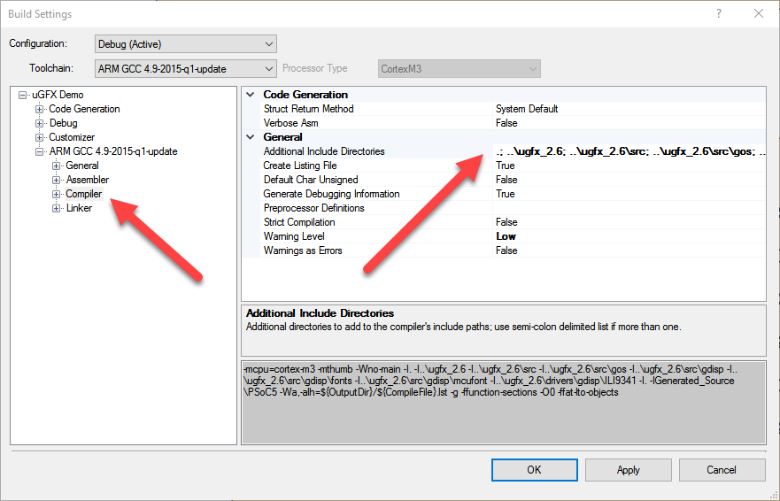
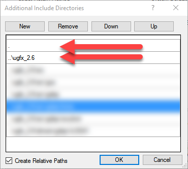
Next, we need to add the top level uGFX library directory and the driver directory to the compiler include path. This is done in the Build Settings dialog:
At this stage you have successfully added the µGFX library to an existing PSoC Creator project and you should be able to compile without any errors after including #include <gfx.h> and calling gfxInit() in your main() code (if the requirements of the underlying system are met):
#include "gfx.h"

int main (void)
{
    // Initialize hardware and underlying system (if any) BEFORE calling gfxInit()

    gfxInit();

    while(1) {
        gfxSleepMilliseconds(500);
    }
}
Adding Drivers
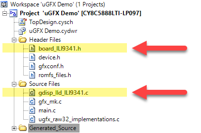
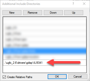
Drivers are being added by adding the drivers directory to the compiler include path and adding the driver source file(s) to the project file tree. The following is an example showing how to add the ILI9341 driver to the PSoC Creator project. However, adding any other uGFX drivers for displays, touchscreen, audio and so on is exactly the same.
The following steps need to be performed:
- Add the driver directory to the compiler include path (
../ugfx_2.6/drivers/gdisp/ILI9341in this case) - Copy the board file template from the driver directory to your project (
board_ILI9341.hin this case) - Add the driver source file to the project tree (
gdisp_lld_ILI9341.cin this case)
Hardware
Unlike conventional microcontrollers, the PSoC family doesn't have pre-made peripherals. This section gives examples to implement some of the basic features required to create a useful & run-able µGFX application. Please note that the components and their configuration shown here are examples. They are in no way optimized for a specific target or a specific application.
Systick
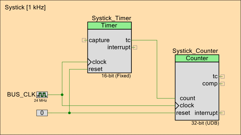
If running µGFX baremetal on the PSoC (without an underlying operating system), two systick functions have to be implemented (see baremetal for more details). The standard components library of the PSoC Creator schematic editor doesn't feature a pre-made systick component. Therefore, this has to built manually using a conventional timer and a counter.
In this example, we are using a 1 kHz timer and a 32-bit counter. However, other setups are possible:
The two systick functions of the raw32 port can be implemented like this:
systemticks_t gfxSystemTicks(void)
{
    // We use a counter with a 1kHz clock source
	return Systick_Counter_ReadCounter();
}

systemticks_t gfxMillisecondsToTicks(delaytime_t ms)
{
    // We use a counter with a 1kHz clock source
	return ms;
}
However, we still have to manually start and enable the timer and the counter. For this, we add another function and modify the
void raw32Init(void)
{
    // Initialize the systick components
    Systick_Timer_Start();
    Systick_Counter_Start();
}
Now we use the GFX_OS_PRE_INIT_FUNCTION configuration macro in the configuration file to tell µGFX to call this initialization function that enables the systick components before doing anything else:
#define GFX_OS_PRE_INIT_FUNCTION raw32InitNote: There is also an unofficial systick component available from a Cypress employee at the Cypress forum. The advantage of that component is that it uses the native systick timer of the Cortex-M. The reason that component isn't used in this example is because it's not part of the official Cypress libraries. Link.
SPI
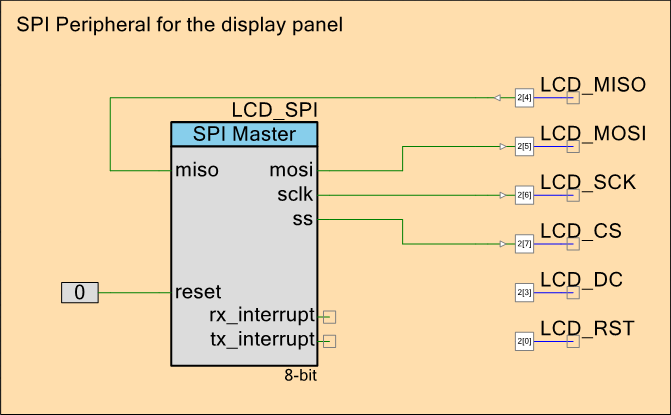
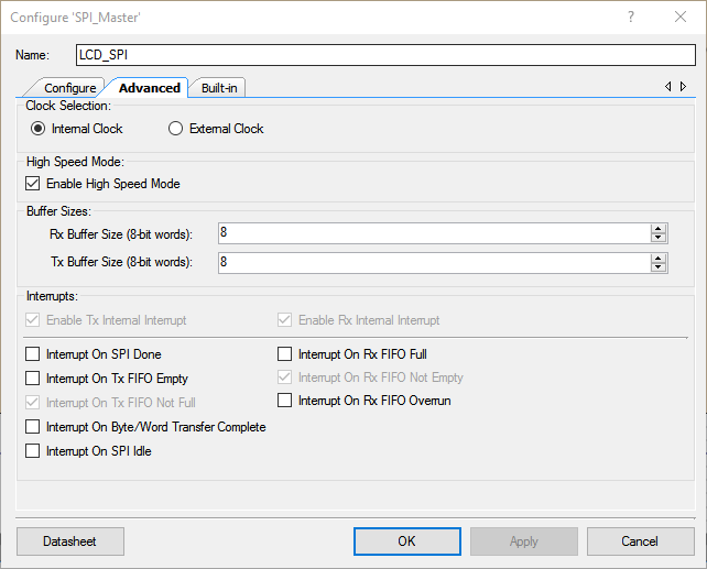
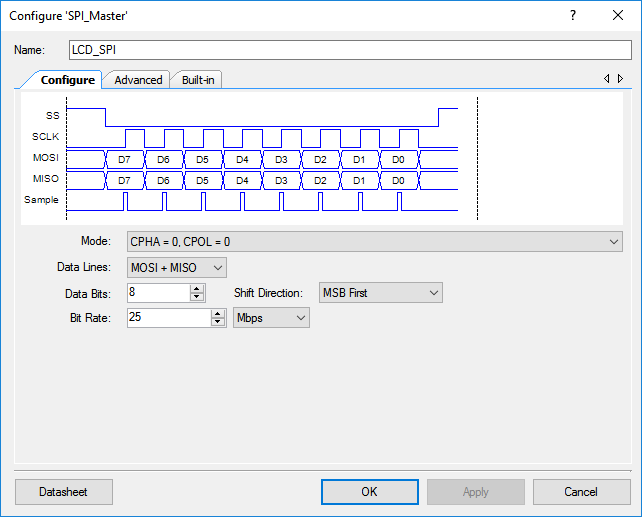
In our example project we are using an ILI9341 display module connected over SPI. For this, we need to add an SPI component to the PSoC project and wire it up to the external pins to which the actual display is connected to.
Note that in case of you want to connect a touchscreen controller with an SPI interface you want to use a second SPI component that is dedicated to the touchscreen. Using the same SPI component for both the display and the touchscreen massively restricts the display performance.
Examples
Various example projects can be found in the downloads section. Use the search to find projects that suit your setup.
